
Using an Arduino – Coding a Bicolour LED Grid to Create Math Patterns
By Chris Yiu, Western University
Chris is a graduate student at Western University. He holds bachelor degrees in medical sciences as well as computer science. He is currently studying his masters in computer science, with an interest in virtual/augmented reality and introducing computer science to students at a younger age.
Let’s code an 8×8 grid of LED lights to animate cool math patterns, like the one below, which shows that “Odd numbers hide in squares!”
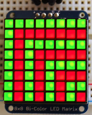 8 x 8 grid of LED lights that shows odd numbers hiding in a square
Do you see the odd numbers 1, 3, 5, 7, 9, 11, 13 and 15 hiding inside the square?
I wonder: “Where do even numbers hide?”
Let’s set up the LED matrix to the backpack
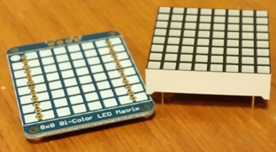 Setting up the LED matrix to the backpack
Here’s the matrix with the backpack – just two pieces.
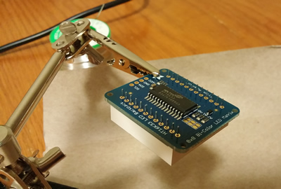 Just a little soldering required
 All done!
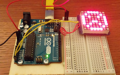
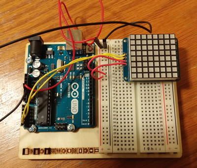 Here it is wired up to the Arduino Uno
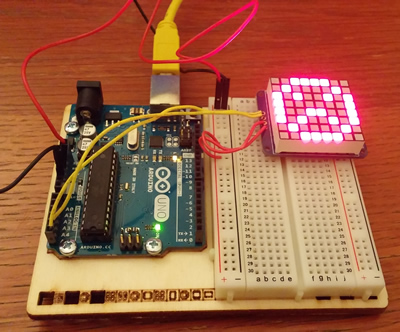
It works!
Connecting the Matrix
Once you have the matrix created, you’ll need to connect it to the Uno. The matrix comes with a four (or maybe six) pin header that you can use to pin the matrix down to the board and then solder – I chose not to solder it so that it is easier to remove in the event that we want to use the board for something else.
Before connecting the matrix, make sure that the Uno board is powered off. The matrix has four inputs – two are for power (positive and negative). The + connects to the 5V on the Uno, while the – connects to the ground. The other two are the clock (CLK), shown as a C on the top of the board, and data (DAT) input, shown as a D on the top of the board. The clock connects to the A5 analog on the Uno, while the data connects to the A4.
Programming the Matrix
Now that we have the matrix all set up, we can start programming it! Here’s what you’ll need:
- Arduino Integrated Development Environment (IDE) – You can get it here (http://arduino.cc/en/main/software)
The Uno should come with a USB cable that you can plug right into it to upload the data. Simply plug the cable into the Uno and you’ll be good to go! You should see a few lights on the board when you plug it in.
Installing the Required Libraries
The libraries are like the tools of a workbench. They provide us with things we need to make sure the matrix works the way it’s supposed to. In a more technical way, they provide us with the definitions of some procedures we’re going to be using (such as drawing pixels, keeping track of the time, and so on). Here’s how to install the libraries:
- Visit this website (https://github.com/adafruit/Adafruit-LED-Backpack-Library) and click on the ‘Download zip’ button
- Extract the zip wherever you like and rename the folder to ‘Adafruit_LEDBackpack’ (there should be a LEDBackpack’.cpp and LEDBackpack’.h file inside the renamed folder)
- Move the folder into the \Arduino\Libraries folder. This will depend on where you’ve installed Arduino, typically it will be in either C:\Program Files (x86)\Arduino or C:\Program Files\Arduino
- You’re done! You can verify that you’ve installed the library correctly by opening up the Arduino IDE, and going to File–>Examples Library and finding Adafruit_LEDBackpack in the list there. If it isn’t there, then there was a problem installing the libraries – try again from the beginning step
There is one other required library, installed the same way as the previous (except you don’t have to rename the folder – just unzip it and move it into your \Arduino\Libraries folder)
- Adafruit_GFX (https://github.com/adafruit/Adafruit-GFX-Library) – this library is for illuminating the matrix
You can check that the library is installed the same way we did for the Adafruit_LEDBackpack library – look inside Sketch –> Import Library and make sure Adafruit_GFX is listed there.
Getting Started
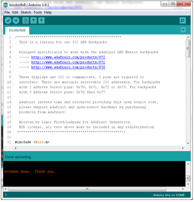
Now that we have all of our tools ready, let’s get into the programming! Launch the Arduino IDE and open up the sample provided with this tutorial. If you can’t find it, you can always get the sample from the library by going to File –> Examples –> Adafruit_LEDBackpack –> Bicolour8x8 (make sure to save it somewhere new). You should get a window that looks like this:
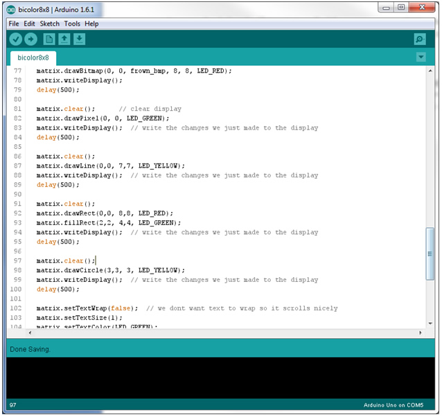
This is what the board comes with by default. Let’s upload it just to make sure it works. Before we do the upload, we need to make sure we’ve selected the right tools. Under Tools –> Board, make sure Arduino Uno is selected as the board type. Also look under Tools –> Ports, and make sure that you select the one that says (Arduino Uno) in brackets.
First, click the checkmark to verify that the code compiles (it should, they gave it to us after all!). You should get a verification that the compile went okay:
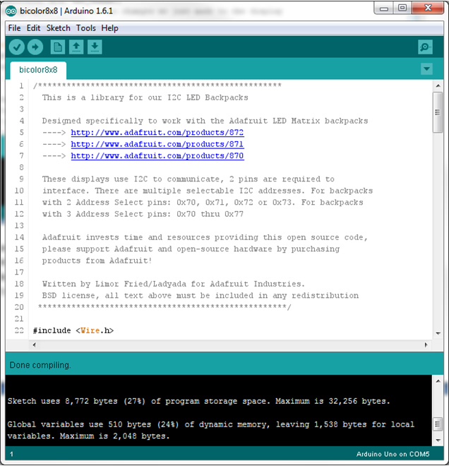
Now we can upload the code to the matrix! Click on the arrow next to the checkmark at the top – this will upload the code onto the Uno.
Once it tells you the upload is done, the matrix should reset and perform its basic routines. Now we know how to get code from the computer onto the Uno!
Programming the Matrix
There are a few pieces of code that are necessary to get the matrix working. These reside inside the setup() function:
void setup() {
Serial.begin(9600);
matrix.begin(0x70); // pass in the address
}
These two lines of code initialize the matrix and tell the Uno its address so that it can communicate with it. Make sure you keep these two lines of code in so that the matrix works!
Let’s get rid of everything else in the sample – this means all of the code inside the loop() function, and the static constants that they have. Our code should look pretty short and empty now:
#include <Wire.h>
#include “Adafruit_LEDBackpack.h”
#include “Adafruit_GFX.h”
Adafruit_BicolorMatrix matrix = Adafruit_BicolorMatrix();
void setup() {
Serial.begin(9600);
Serial.println(“8×8 LED Matrix Test”);
matrix.begin(0x70); // pass in the address
}
void loop() {
}
The loop function is where all the magic happens. This function is repeated over and over again forever, so anything that we want the matrix to do either needs to be in here, or needs to be called from here. Let’s start off with drawing a few pixels. Inside the loop function, try inserting the following code:
void loop() {
matrix.drawPixel(0, 0, LED_RED);
matrix.drawPixel(1, 0, LED_GREEN);
matrix.drawPixel(2, 0, LED_YELLOW);
matrix.writeDisplay();
}
Can you guess what this code will do? The drawPixel function simply lights up one of the pixels with a colour. The pixel is given by an (x, y) coordinate, with (0,0) being the top left. The colours are specified with LED_GREEN, LED_RED, and LED_YELLOW. matrix.writeDisplay() tells the matrix to show whatever the code has made it do – this line is crucial to making the matrix display what you want. Don’t forget to call matrix.writeDisplay() whenever you want it to show something!
We can draw things by lighting up individual pixels, but this can get very tedious very quick. Fortunately, there are other functions that will help us draw what we want without too many lines of code. Let’s take a look at the drawLine() function:
void loop() {
matrix.drawPixel(0, 0, LED_RED);
matrix.drawPixel(1, 0, LED_GREEN);
matrix.drawPixel(2, 0, LED_YELLOW);
matrix.drawLine(0, 1, 7, 1, LED_RED);
matrix.drawLine(2, 2, 7, 2, LED_GREEN);
matrix.drawLine(4, 3, 7, 3, LED_YELLOW);
matrix.writeDisplay();
}
As the name suggests, the drawLine() function draws a line from point A to point B. Point A is given by the first two numbers as x and y coordinates, and point B is given as the next two numbers, again as x and y coordinates. The colour is given last.
drawLine(x1, y1, x2, y2, colour)
As always, remember to call writeDisplay() after drawing everything!
Drawing Patterns
We now know how to light things up on the matrix, but what about drawing patterns that change over time? Here we’ll look at how to do that using two functions – delay() and clear():
void loop() {
matrix.drawPixel(0, 0, LED_RED);
matrix.drawPixel(1, 0, LED_GREEN);
matrix.drawPixel(2, 0, LED_YELLOW);
matrix.writeDisplay();
delay (1000);
matrix.drawLine(0, 1, 7, 1, LED_RED);
matrix.writeDisplay();
delay (1000);
matrix.drawLine(2, 2, 7, 2, LED_GREEN);
matrix.writeDisplay();
delay (1000);
matrix.drawLine(4, 3, 7, 3, LED_YELLOW);
matrix.writeDisplay();
delay (1000);
matrix.clear();
matrix.writeDisplay();
delay (1000);
}
You’ll notice that in the code, we now call matrix.writeDisplay() more than once. The delay function makes the Uno wait for the specified amount of milliseconds before continuing on. What we’ve done here is told the matrix to show something, and then told it to wait a second before showing the next thing. This gives us the changing pattern that you see on the matrix.
Remember that once a pixel is turned on, it will remain on until you tell it to turn off. In the sample above, we used the matrix.clear() function to turn off all of the pixels, but what if you only want to turn off a select number of pixels? It’s done the same way as turning on the pixels, but instead of giving it a colour (e.g. LED_GREEN), you tell it to turn off (LED_OFF). Think of it as using white-out – you’re drawing the pixel with the ‘off’ colour.
void loop() {
matrix.drawPixel(0, 0, LED_RED);
matrix.drawPixel(1, 0, LED_GREEN);
matrix.drawPixel(2, 0, LED_YELLOW);
matrix.writeDisplay();
delay (1000);
matrix.drawPixel(0, 0, LED_OFF);
matrix.drawLine(0, 1, 7, 1, LED_RED);
matrix.writeDisplay();
delay (1000);
matrix.drawPixel(1, 0, LED_OFF);
matrix.drawLine(2, 2, 7, 2, LED_GREEN);
matrix.writeDisplay();
delay (1000);
matrix.drawPixel(2, 0, LED_OFF);
matrix.drawLine(4, 3, 7, 3, LED_YELLOW);
matrix.writeDisplay();
delay (1000);
matrix.clear();
matrix.writeDisplay();
delay (1000);
}
Defining Functions
Our loop function is starting to get pretty long. If we decide that we want to add some more patterns in there, it’s going to be very hard to read! Fortunately there’s a solution to this – functions. Functions are like a set of instructions. You can place any number of instructions inside them, and then you can call the function later and ask it to perform whatever instructions you placed inside. This is often used when something is going to be repeated several times…like our writeDisplay() and delay() combination. We can create a function with those instructions inside it, and then call the function instead:
void writeAndWait()
{
matrix.writeDisplay();
delay (1000);
}
void loop() {
matrix.drawPixel(0, 0, LED_RED);
matrix.drawPixel(1, 0, LED_GREEN);
matrix.drawPixel(2, 0, LED_YELLOW);
writeAndWait();
matrix.drawPixel(0, 0, LED_OFF);
matrix.drawLine(0, 1, 7, 1, LED_RED);
writeAndWait();
matrix.drawPixel(1, 0, LED_OFF);
matrix.drawLine(2, 2, 7, 2, LED_GREEN);
writeAndWait();
matrix.drawPixel(2, 0, LED_OFF);
matrix.drawLine(4, 3, 7, 3, LED_YELLOW);
writeAndWait();
matrix.clear();
writeAndWait();
}
Here we added the function writeAndWait(). All it does is tell the matrix to writeDisplay(), and then delay(1000). The ‘void’ in front of the function name means that it does not return any values – you can create functions that also return something. In this case, we don’t need it to return anything, just execute a few instructions.
You may also notice the brackets after the function name (). The brackets contain parameters – things that you need to give to the function. In this case, we have not specified a parameter, but maybe it could be useful to us:
void writeAndWait(int delayTimeInMilliseconds)
{
matrix.writeDisplay();
delay (delayTimeInMilliseconds);
}
void loop() {
matrix.drawPixel(0, 0, LED_RED);
matrix.drawPixel(1, 0, LED_GREEN);
matrix.drawPixel(2, 0, LED_YELLOW);
writeAndWait(1000);
matrix.drawPixel(0, 0, LED_OFF);
matrix.drawLine(0, 1, 7, 1, LED_RED);
writeAndWait(500);
matrix.drawPixel(1, 0, LED_OFF);
matrix.drawLine(2, 2, 7, 2, LED_GREEN);
writeAndWait(500);
matrix.drawPixel(2, 0, LED_OFF);
matrix.drawLine(4, 3, 7, 3, LED_YELLOW);
writeAndWait(500);
matrix.clear();
writeAndWait(500);
}
Notice now that there is something inside those brackets. Whenever we want to call this function, we have to give it an int (a number). This number represents how long the Uno should wait before continuing on. This allows us to change the delay without changing the function – you’ll notice that some of the writeAndWait() function calls only have 500 milliseconds of delay instead of 1000.
Providing Input
The Uno is an awesome board because it has so many capabilities. One of the neat things we can do is make the matrix respond to an input, like a button. For this, you’ll need the following parts from your Uno kit:
- 1 button
- 2 wires
- 1 10k Ohm resister
- 1 button
You’ll also want an extra two wires to power the side of the board. You can connect the matrix power to these sides as well – here’s what the finished product will look like:
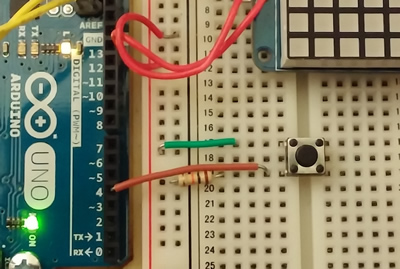
Notice how the power for the matrix now comes from the side columns instead of directly from the power source. We need the power to complete the circuit for our button.
Complete the circuit as shown in the picture above. If you’re not sure exactly how it works, the button circuit is taken exactly from project 2 of the Arduino projects book (the spaceship interface).
Make sure that the wire from the circuit to the board goes into a digital pin. The digital pins are those numbered without the ~ in front of the number (2, 4, 7, 8). The pins with the ~ are PWM pins (also digital, but give an analog input/output). Think of digital as a light switch (on or off) and analog as a volume knob (low to high).
In the code, the first thing we need to do is tell the board that we are using one of the pins as an input signal. This is done in the setup function:
void setup() {
Serial.begin(9600);
// declare the switch pin as an input
pinMode(4, INPUT);
matrix.begin(0x70); // pass in the address
}
This tells the board to read that pin as an input, and allows us to access its reading. Great, so now how do we actually make it do something?
It is important to understand what is happening inside the circuit with the button in it. The circuit is not complete when the button isn’t pressed, so the input will read as low (there’s no voltage). When the circuit is completed the voltage can go through the circuit to the input, so it will read as high (there’s voltage here!). Whenever the button is pressed, the Uno will read the input as being high.
If we want our code to do something when the button is pressed, then we want to check if the input is high. Let’s take a look at the code and see how to do it:
void setup() {
Serial.begin(9600);
// declare the switch pin as an input
pinMode(4, INPUT);
matrix.begin(0x70); // pass in the address
}
void writeAndWait(int delayTimeInMilliseconds)
{
matrix.writeDisplay();
delay (delayTimeInMilliseconds);
}
void loop() {
int input = digitalRead(4);
if (input == HIGH)
{
matrix.drawPixel(0, 0, LED_RED);
matrix.drawPixel(1, 0, LED_GREEN);
matrix.drawPixel(2, 0, LED_YELLOW);
writeAndWait(1000);
matrix.drawPixel(0, 0, LED_OFF);
matrix.drawLine(0, 1, 7, 1, LED_RED);
writeAndWait(1000);
matrix.drawPixel(1, 0, LED_OFF);
matrix.drawLine(2, 2, 7, 2, LED_GREEN);
writeAndWait(1000);
matrix.drawPixel(2, 0, LED_OFF);
matrix.drawLine(4, 3, 7, 3, LED_YELLOW);
writeAndWait(1000);
}
matrix.clear();
matrix.writeDisplay();
}
First we need to take the reading from the input and store it somewhere (in this case we store it in a variable called input). The reading is done using the digitalRead() function – just give the number of the pin, and it will tell you if it is HIGH or LOW. Then we have an if statement which says, if the reading is high, then I want you to draw the pattern. This button acts like a ‘play’ button – it starts the pattern up when it is pressed.
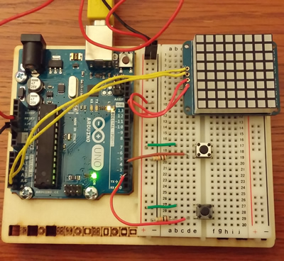
You can add as many buttons as you want (or can fit onto the board). Here’s an image of two buttons – what other things could you control with a second input?
Link to printable PDF: math-patterns-on-LED-matrix-MnC-article
A project by George Gadanidis
Western University
www.researchideas.ca